Irrigating greenhouse and nursery crops based on soil moisture measurement
By Loren Oki
All ag producers in California, including greenhouse and nursery growers, are impacted by the multi-year drought we are experiencing here. Greenhouse and nursery growers may be particularly affected because of the intensive production of crops of plants grown at high densities either in the ground or in containers. High productivity is almost always linked to greater use rates of resources, including water.
To improve the efficiency of water used for irrigation, changes to management practices have been applied to application methods and scheduling. Alterations to application methods have included changing from impact sprinklers to rotors to improve distribution uniformity, expanding the use of drip irrigation systems, and managing water pressure.
Improving irrigation scheduling is another way to reduce water use. Irrigating plants only when it is needed and applying only the amount that is necessary optimizes irrigation efficiency and leads to reduced water use. Improving irrigation scheduling might utilize weather information, which affects plant water demand, or measuring soil moisture content.
When utilizing weather to manage irrigation, there needs to be an understanding of how weather relates to the amount of water that a plant would use. This relationship is dependent on a number of things including: plant species, size of the plant canopy, soil characteristics, irrigation history, and others. So, although using this method can be very effective, it is merely an estimation of plant water use.
Plants obtain almost all of water needed from the soil. So, measuring the amount of water in the soil that is available to plants can be an efficient method to managing irrigation: When the soil is dry, apply water; and only apply enough to re-wet to a specific level.
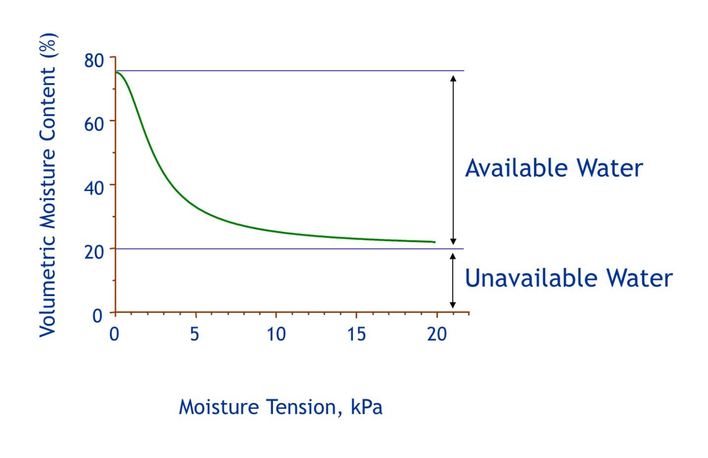
There are two main types of soil moisture sensors and they can be grouped by the characteristic they measure. One group measures an energy component of soil water called “matric potential” (MP), which describes how tightly the soil holds onto water. This is the force that plants need to overcome to obtain the water. As soil dries, it holds onto the water that remains in it more tightly. Moist soils “give up” water more readily than drier soils, so it is easier for a plant to extract water from a moist soil compared to a dry one. There is an amount of water that plants cannot extract because it is very tightly held by the soil and is called “unavailable water”. Matric potential is measured in units of kPa (kilopascals) or MPa (megapascals). A saturated soil has a measurement of 0 kPa and becomes more negative as the soil dries. Soil moisture “tension” is simply the matric potential measurement with the negative sign removed.
The other characteristic measured by sensors is volumetric water content (VWC), the amount of water in the soil. This is usually described as a percentage of the soil volume that is water. For example, a volumetric water content measured at 12% tells us that 1 liter (1,000 mL) of soil contains 120 mL of water. The amount of water that can be held in soil depends on the soil type. VWC would never be 100% since that would mean that there is no soil, but is only water. Field capacities of soils vary from about 20% for a silty soil, 15% for a clay, and 5% for a sandy soil.
There is a relationship between volumetric water content and matric potential. Graphically this is relationship is called a “moisture release curve” and has several synonyms where “water” might be replaced by “moisture” and “release” might be replaced by “retention”, “holding”, or other similar terms. Usually these graphs are configured so that the horizontal X-axis represents matric potential or tension in kPa or MPa. The vertical or Y-axis is volumetric water content in percent.
Sensors that measure matric potential include electrical resistance blocks and tensiometers. Electrical resistance blocks are also known as gypsum block sensors which are simply a plug or block of gypsum into which two electrodes are inserted. As soil moisture changes, the moisture content within the gypsum block also changes which is measured by the resistance between the electrodes embedded in the block. Wetter soil is indicated by lower resistance in the block. The gypsum material also partially removes effects of soil salinity. The name given to these sensors is misleading since it is the conductance, not resistance, between the electrodes that is measured. This requires an alternating current (AC) which is provided by a handheld meter used to read the sensor.
Granular matrix sensors are improvements of gypsum blocks but instead of a block of gypsum, some other medium or “matrix” is used in which the resistance is measured. This matrix might be a fine sand, as in the Watermark (Irrometer Co., Riverside, CA) that improves the speed of the sensor response to changes in soil moisture. This sensor is reconfigured as a cylinder wrapped within a membrane further enclosed in a stainless steel mesh and includes a wafer of gypsum to moderate salinity effects.
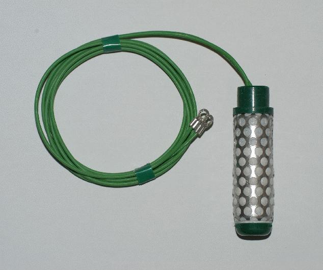
Watermark (Irrometer Co., Riverside, CA) sensor. Photo by L. Oki
Tensiometers are simple instruments consisting of a plastic (typically) tube, a porous ceramic cup at one end, and a vacuum gauge at the other. The tube is filled with water to exclude air and the tensiometer is inserted in to the soil. As the soil dries, water is pulled from the tensiometer through the ceramic into the soil creating a vacuum within the tube that is measured by the gauge. The drier the soil, the greater the pulling force and vacuum. When irrigation occurs, the vacuum in the tube pulls water back into the tube from the soil which reduces the vacuum. The “pulling” force of the soil on water is matric potential. The gauges of tensiometers may be labeled in units of centibars (cbar) which is a pressure term. This makes sense since a vacuum is opposite of pressure or, more correctly, is a negative pressure. Fortunately for us, cbar and kPa are the same and can be interchanged. The vacuum gauge can be replaced with a pressure transducer that converts the vacuum to an electrical signal that can be “read” and converted to a measurement. Tensiometers are available in different lengths to be able to place the ceramic tip at different soil depths.
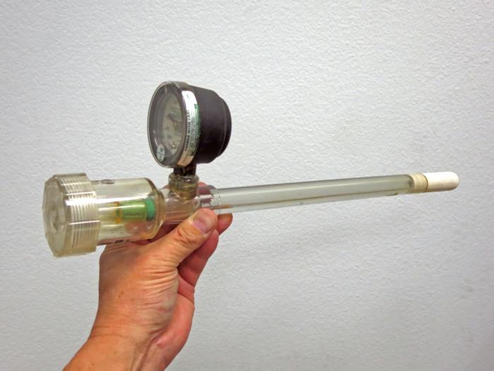
Tensiometer (Irrometer Co., Riverside, CA) Photo by L. Oki
Sensors that measure volumetric water content that are commonly used include time domain reflectometry (TDR), capacitance, and other variations. These sensors measure dielectric permittivity, which is the ability of a nonconducting material to transmit electromagnetic pulses. There are other ways to measure VWC including gravimetric (weighing the soil as it dries), neutron probes, and heat pulse but this article will focus on the dielectric sensors. This discussion will focus on advantages and disadvantages of the different types of sensors and less about how they work. (Editors link here to ST article on gravimetric method for containers)
TDR uses an electronic module that generates an electromagnetic pulse through a cable to the sensor exposed to the soil. As the pulse travels down the rods, the characteristics of the pulse changes depending on water content, among other things. The benefits of this method is that it is very fast with results returning from sensors in microseconds (μS) and the sensors are inexpensive and rugged. The electronics, however, are very expensive but can support large numbers of sensors. TDR can also measure salinity. This method is also affected by high organic matter content, high salinity levels, and clay soils.
Capacitance sensors are more affordable for greenhouse and nursery growers compared to TDR, but also measure dielectric permittivity. The sensors are more expensive than TDR sensors, but “reading” them can be simple.
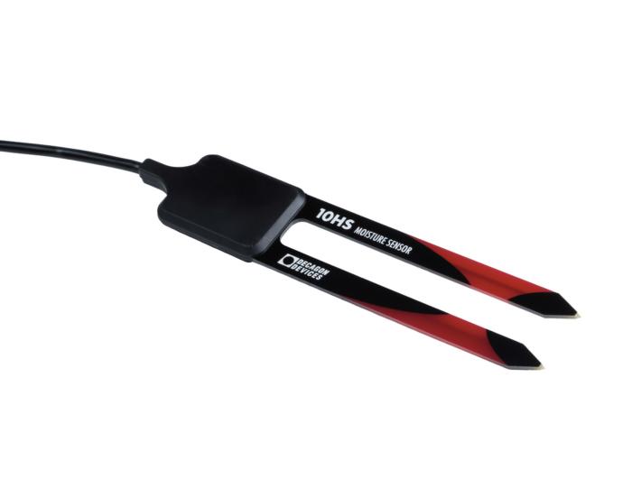
Decagon 10HS sensor (Decagon Devices, Pullman, WA) Image obtained from http://www.decagon.com/products/soils/volumetric-water-content-sensors/10hs-large-soil-moisture-sensor/
Understanding the data
The information collected about changes in soil moisture is used to assist with the management or control of irrigation. But we need to understand how to interpret the information that comes from the sensors. Remember that the type of data that is collected since VWC and MP are very different and depends on the type of sensor used. So, be clear which type is being reported. Data of volumetric water content (VWC) will change from a relatively higher value when the soil is wet and will decline as the soil dries. In comparison, tension (remember that “tension” is “matric potential (MP)” without the negative sign) will start out low when the soil is wet and increase as it dries. Tensions will fall to 0 kPa when the soil is saturated. Tensions can be less than 0 if the soil is supersaturated and can occur during irrigation (see lower portion of the soil moisture tension figure). Once the irrigation is stopped, the tension will change as excess water drains from the soil and briefly stabilize at some level. This information can be used to reduce over-irrigation by avoiding application durations that result in negative tension values.
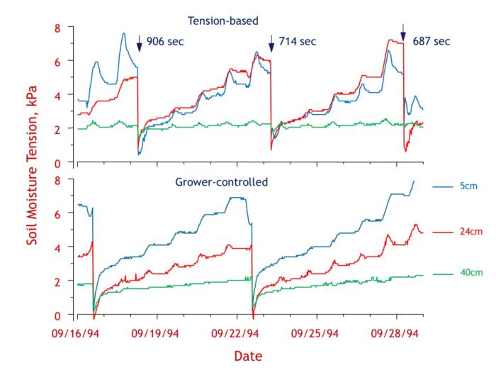
Soil moisture tension data. A comparison of soil moisture in rose production bed where irrigation is controlled by the grower (lower) and by soil tension (upper). The portions of the curves are flatter are during the night when transpiration rates are low. Increases in tension occur during the day but can fall in the evening as water moves upward from wetter, deeper soil. The times in the upper graph are the total durations the valve was on. Where tensions fall below 0 kPa (lower graph), the soil cannot hold onto excess water and runoff had occurred. Data and graphic by L. Oki
If a system using soil moisture sensing is installed to control irrigation, it is a good idea to disable the irrigation control part of the system. Continue to irrigation as usual and collect data of soil moisture for awhile until you have good understanding of what the data represents. Pay particular attention to the data just before irrigations occur and try to link that to the condition of the plants before the irrigation. If plants show any stress symptoms, you may be able to relate those symptoms to soil water status and can use the soil water data as ones to avoid. Also continue to record the duration of the irrigations as that will be helpful when programming irrigation control.
Once you are comfortable with understanding the data, turn on the irrigation control feature. You will probably be required to enter a “dry set point”, the level when irrigation is needed and either a “wet set point” or the duration of the irrigation. Use the knowledge you have gained from observing the data to help you determine what that set point is. You should know that applying irrigations in short “pulses” is more efficient than applying water in a single long application. The shorter pulses apply water and the interval between the applications allows the applied water to be absorbed by the soil. You’ll need to do some trials to determine the duration of the pulse and the interval between the pulses. It is highly likely that when pulse irrigation is used, that there will be a reduction in the total length of time the valve was on compared to a single longer “on-time” duration.
It is probably obvious that when the irrigation feature is enabled, it needs to be watched very closely to make sure the irrigations are applied properly. It will take some time until there is a level of “trust” in the system. Keep an eye on the soil moisture measurements and plant condition. If both appear to be “okay” even though irrigation might appear to be inadequate, then the irrigation is also probably okay. Adjustments will need to take place if the plant condition is not as desired.
In addition to understanding that soil type determines the amount of water that will be available to plants (known as “plant available water”) another important parameter is how fast water can enter the (known as “infiltration rate” or “intake rate”). For example when comparing sandy and clay soils, sandy ones hold less water but have a high intake rate, whereas clay soils hold more water but the infiltration rate is low. Water should be applied to sandy soils frequently in short durations and slowly, for longer durations, and less frequently to clay soils. Knowing the intake rate can also affect the type of application since different sprinklers and drip systems apply water at different rates. If an intake rate of a soil is 0.2 inches per hour, then runoff will occur if the precipitation rate of the irrigation system is 1.0 in/hr. In that case, either the systems would need to be modified to reduce the application rate or short pulses will be required to allow applied water to be absorbed into the soil before another pulse is applied.
What’s on the horizon
Wireless communication isn’t new to you if you have a cell phone and most of us do. But it is also becoming more prevalent in the case of irrigation control and sensing. There are wireless nodes that include a radio package and a control function that allows a base station running an irrigation program to communicate with the node to turn valves on and off. Some of these nodes also include the ability to attach a soil moisture or other sensor. Communication can occur directly between the node and the base or through a wireless mesh network where the signal hops through nodes until it reaches the node where control needs to occur. An advantage of these mesh networks is unlimited distance as long as each node is within range of another. Another advantage is that as long as there are alternate communication paths between nodes and should a node fail, the communication link can be re-established if there is another working node within range.
There is also the ability for irrigation managers to access information using an interface on a smart phone. Most of us carry one nowadays, so it makes sense to use it to adjust irrigation or modify a program due to crop changes that are observed in the field instead of having to return to the base station to make those adjustments. The control program can also be integrated with other parameters that affect disease pressure or reduce or delay irrigation if rain is forecast, for example.
Irrigation based on soil moisture measurement has been around for awhile (did you notice the dates on the soil moisture tension graphs?), but it hasn’t been until recently that computers, programs, user interfaces, wireless communications, and other features have developed sufficiently and come together to make it easy for grower to implement and manage. When in use and properly managed, irrigation systems using soil moisture sensors can reduce water use, reduce irrigation runoff, improve water use efficiency, and provide growers information to assist in crop production.
References
Oki, L.R., J.H. Lieth, and S.A. Tjosvold. 2001. Irrigation of Rosa hybrida L. 'Kardinal' based on soil moisture tension increases productivity and flower quality. Acta Hort. (ISHS) 547: 213-219. http://www.actahort.org/books/547/547_25.htm
Coates, R.W., M.J. Delwiche, R.Y. Evans, L.R. Oki, and P.H. Brown. 2007. Site-Specific Water and Nutrient Application by Wireless Valve Controller Network. ASABE Paper No. 072247. St. Joseph, MI: ASABE. https://elibrary.asabe.org/azdez.asp?JID=5&AID=23373&CID=min2007&T=2


