- Author: Michael D Cahn
- Author: David Chambers
A tensiometer is a very useful tool for monitoring soil moisture status of vegetable and berry crops. Compared to other sensors that often require equipment such as dataloggers or a computer to collect readings, tensiometers can be easily read by irrigators in the field. Also, tensiometer readings are not affected by variations in soil texture, temperature, and salinity and they can operate without electricity (no batteries needed).
What is tension? Tensiometers measure soil moisture in units of negative pressure also known as tension. Tension is a measure of the force that plant roots need to exert to pull water from the soil pores. Large pores hold water with less force than small pores. As plants extract moisture from the soil, water is first taken up from the largest pores. As the soil dries roots need to exert more force to pull water from the smaller pores. Hence, high tension values mean that the soil is becoming dry.
How do tensiometers work? Tensiometers are filled with water (preferably distilled) that has been degassed by boiling. A key component of the tensiometer is a porous ceramic cup which allows water in the shaft of the tensiometer to freely pass into the soil without air bleeding though the small pores in the cup (Fig. 1). If the soil is not saturated, water will move from inside the cup into the unfilled soil pores. Because air cannot replace the space vacated by the exiting water, a vacuum develops in the shaft of the tensiometer that can be measured with an accurate gauge. Water will stop migrating from inside the tensiometer cup into the soil when the internal vacuum pressure of the tensiometer equals the soil tension, or the force needed to pull water from the soil pores. The vacuum gauge measures tension in units of kPa or cbars, which are equivalent (1 kPa = 1 cbar).
Interpretation of tension readings Because the tension value provides a sense of how much energy a plant would need to exert to suck water from the soil, tensiometer readings can be easily related to water stress in crops. At high tension values a plant experiences more water stress and growth slows. In addition, a tension reading has a similar meaning in terms of water stress whether the soil has a sandy, clay or loam texture.
Reliability of tensiometers The one Achilles' heal or weakness of the tensiometer is that if any air leaks into the instrument it will not retain a vacuum and the readings will be unreliable. There are several brands of commercial tensiometers available. Some are relatively inexpensive and simple to use, and others are more complex and can be interfaced with dataloggers to provide continuous readings throughout the day. Based on our experience, some of the most popular commercially available tensiometers often leak air and lose vacuum pressure, and in many cases the gauges do not provide accurate readings or are not durable. The loss of vacuum pressure means that the tensiometers need to be frequently refilled with degassed water. Also, irrigators may mistake a low reading to indicate that a crop has adequate moisture when in reality the soil may be dry.
A dependable tensiometer design We designed and tested a version of a tensiometer in 2018 that was simple to build and provided accurate readings for a material cost of less than $55 . The design improved the ability of the instrument to retain a vacuum at high tensions. Under moderately moist soil conditions the tensiometer usually required refilling with degassed water less than once per month. Even when the soil dried to tensions above the maximum range of the tensiometer (> 80 kPa), these tensiometers continued to hold a vacuum for about two weeks until all of the water in the shaft was depleted.
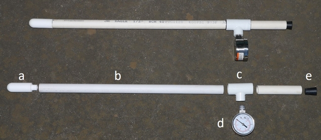
The following paragraphs describe the materials needed (Fig. 2) and procedures to build a tensiometer. The vendors of the materials are examples of ones that we use, but you may identify different or cheaper sources for these components. By carefully following these instructions, one should be able to build a dependable tensiometer that provides accurate tension readings. An update to this design can also be found in a more recent blog article.
Materials needed:
Ceramic cups
Vender: SoilMoisture Equipment Corporation, Santa Barbara CA (805-964-3525) Part Number 0655X01-B01M3, Dimensions: 0.875 inch OD x 2.75 inch length. Cost: $30.80 ea.
Epoxy (ceramic/plastic)
Vender: SoilMoisture Equipment Corporation, Santa Barbara CA (805-964-3525)
Part Number 0980V004, Description: 4 oz: epoxy and 4 oz hardener. Cost: $106 ea. Note that the epoxy/hardener is a sufficient volume to make several hundred tensiometers.
Vacuum gauge
Vender: Zoro.com/Grainger.com Part Number 4FMK3, Description: ¼ inch MNPT 2 inch diameter test vacuum gauge. Cost: $18.09 ea.
#1 size rubber stopper
Vender: Grainger.com Part Number 8DWU6, model RST1-S, Description: 24 mm neck, bottom diam. = 14 mm. Top diam. = 20 mm. Cost: $18.08 / 52 pieces
Schedule 40 PVC pipe (½ inch diameter) Vender: irrigation supply or hardware store
PVC “T”
Vender: irrigation supply or hardware store, Manufacturer: Spears Inc. Part number 402-072, Description: ½ inch slip x ¼ inch threaded reducing "T."
PVC glue (gray) and purple primer
Vender: irrigation supply or hardware store
Gas pipe thread sealant (white or blue paste type)
Vender: irrigation supply or hardware store
Painters masking tape
Vender: hardware store
Petroleum Jelly (Vasoline)
Vender: pharmacy
Tools needed:
- PVC saw or PVC cutting tool
- Aluminum Oxide grinding stone, Manufacturer: Forney Part Number: A11 60028 Description: 7/8 in [23 mm] diam. x 2 inch [50.8mm] length
- Power hand-held drill
- Miter box
- Pocket knife
Procedures
1. Cut PVC pipe sections in the following lengths
1 foot depth tensiometer: top shaft = 4 inches, bottom shaft = 17 inches
2 foot depth tensiometer: top shaft = 4inches, bottom shaft = 30 inches
It is advisable to cut the bottom shaft about 1-inch longer than indicated above and then carefully cut the lower end of the shaft using the miter box or electric miter saw to assure that it is cut at a 90-degree angle. The ceramic cup will fit crooked on the end of the shaft if the cut deviates from 90 degrees.
- First glue the top shaft and then the bottom shaft to the ½ PVC “T” using the PVC glue. Make sure that you do not glue the end of the bottom shaft that was trimmed to 90 degrees. In a well-ventilated location, apply PVC primer to both the end of the shaft and the inside of the “slip” end of the “T”. Then apply gray PVC glue to both sides, and push the parts together, and hold in place for about 30 seconds to 1 minute. Tip: slightly twist the parts by about 30 degrees immediately after gluing to assure that the parts are secure. Also cover the non-glued areas with painter's tape to prevent the outside from becoming covered with glue.
- Slightly bevel the inside of the lower end of the bottom shaft using the handheld drill and grinding stone (Fig. 3). Alternatively, one can use a knife to bevel the end. Whether using the drill or the knife to bevel the inside of the pipe, stop periodically and test fit the ceramic cup. This way you will not remove too much material, and will quickly get a feel for the appropriate amount to remove.
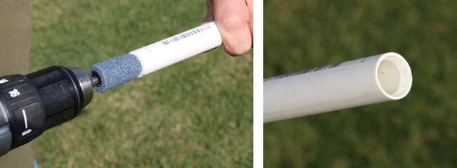 Figure 3. A drill is used to bevel the lower end of the tensiometer shaft to accommodate the ceramic cup.
 - Use epoxy to glue the ceramic cup to the lower end of the bottom shaft. Protect the ceramic cup during the gluing process by covering the outside with painter's tape (Fig. 4). Check that the ceramic cup fits snuggly into the PVC tube and is aligned straight. If using the epoxy from SoilMoisture equipment epoxy, mix up 1-part epoxy with 1-part hardener. Mix thoroughly. Only a small amount of epoxy is needed to coat the throat of the ceramic cup and the inside of the PVC tube, so it may be best to glue several tensiometers at the same time so that the epoxy is not wasted. One can usually glue no more than 20 to 40 cups at a time becaue the epoxy begins to cure after an hour. Approximately 20 ml of epoxy is needed for 20 tensiometers. The cure time is temperature dependent. Full cure is 8 hours at 77 °F. It is best to allow more time for curing. After gluing, painter's tape can be used to secure the cup to the shaft. Take care when securing the two with the tape to assure that the cup is aligned with the PVC shaft. Let the glue set for at least 24 hours with the tensiometer supported with the cup-end up in a vertical position. Tip: best if parts are glued at temperatures above 65 °F. More hardener may be needed at lower temperatures. Also, it is advisable to first test a small batch of epoxy to assure that the proportion of hardener to epoxy is enough for epoxy to set up hard.
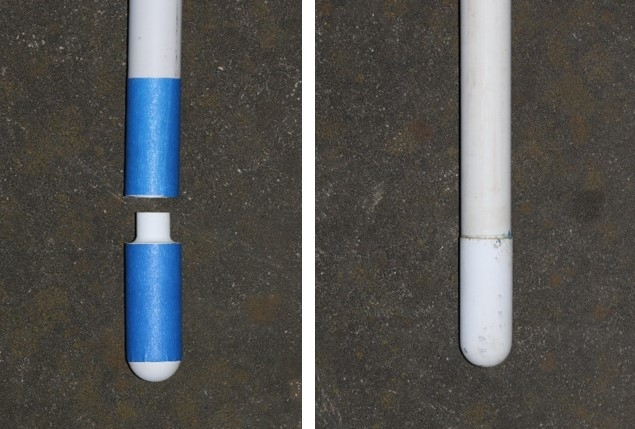 Figure 4. Use painter’s tape to prevent glue from coating the PVC shaft and ceramic cup.
 - Coat the ¼ inch male threads of the gauge with pipe thread sealant and hand screw on the vacuum gauge. Tip: do not over tighten or the PVC “T” will crack!
- Fill the tensiometer fully with degassed distilled water. The water can be degassed by boiling it and allowing it to cool.
- Coat the lower end of the rubber stopper with a thin film of petroleum jelly and insert into the top end of the tensiometer with a light twist to firmly seat the stopper (A loose stopper is the main cause for vacuum leaks).
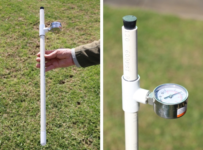 Figure 5. Finished tensiometer is ready for testing.
Preparing the tensiometer for testing and field installation
The tensiometer should be filled with degassed water (preferably distilled) before testing. Tap water will work too, but if it is hard water (contains a high concentrations of calcium and carbonate) it could cause precipitates to form inside the ceramic cup. Boiling will expel much of the dissolved air from the water. We do not recommend using a vacuum pump to remove dissolved air from the water. Boiling works best for degassing water. It also helps to soak the ceramic cup end of the tensiometer in water for a few hours so that the pores of the ceramic cup are saturated before testing and/or installation.
Testing the tensiometer for air (vacuum) leaks
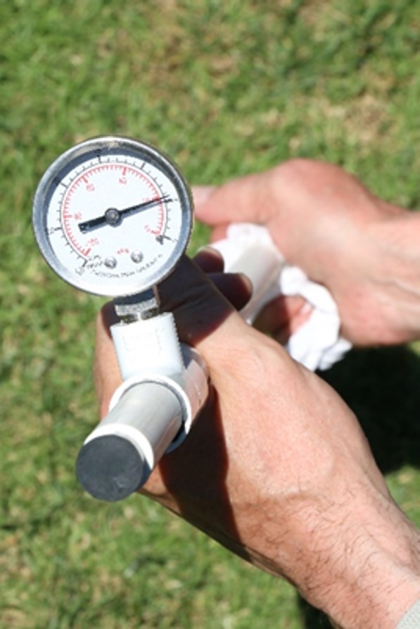
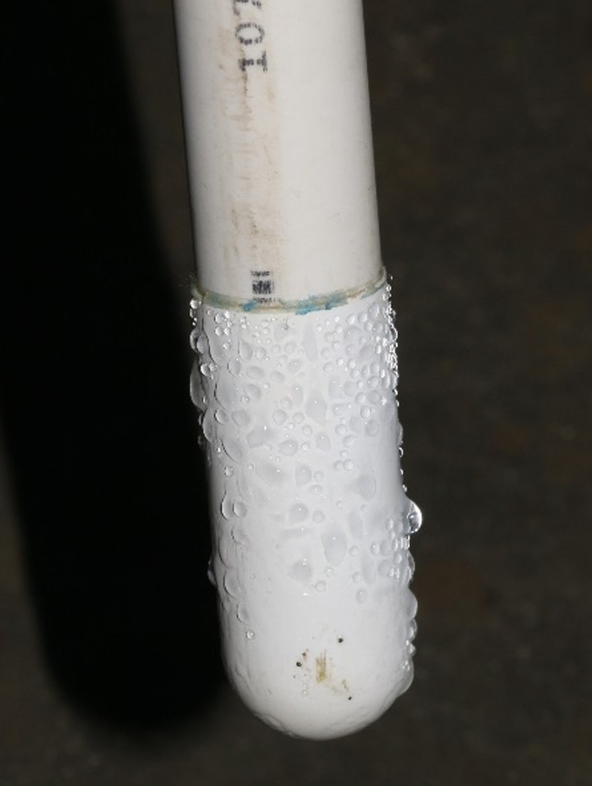
After filling the tensiometer with water and sealing it with a rubber stopper, wrap a dry paper towel on the end of the ceramic cup and hold it tightly (Fig. 6). If the tensiometer is filled with degassed water, the tension should quickly increase to about 20 to 30 kPa as the towel absorbs water from the cup. If the gauge does not increase above 0, air is likely leaking into the tensiometer. Check the glue joints and assure that the stopper is tightly in place.
If the tension quickly increases to more than 20 kPa, then leave the tensiometer out in the sun to assure that the tension rises to above 70 to 80 kPa. This may take some time, minutes to hours, depending on the ambient temperature. If the tension does not increase to a high value, then check glue joints and the stopper. Also check that the gauge is securely threaded into the PVC “T.”
Installing tensiometers in the field
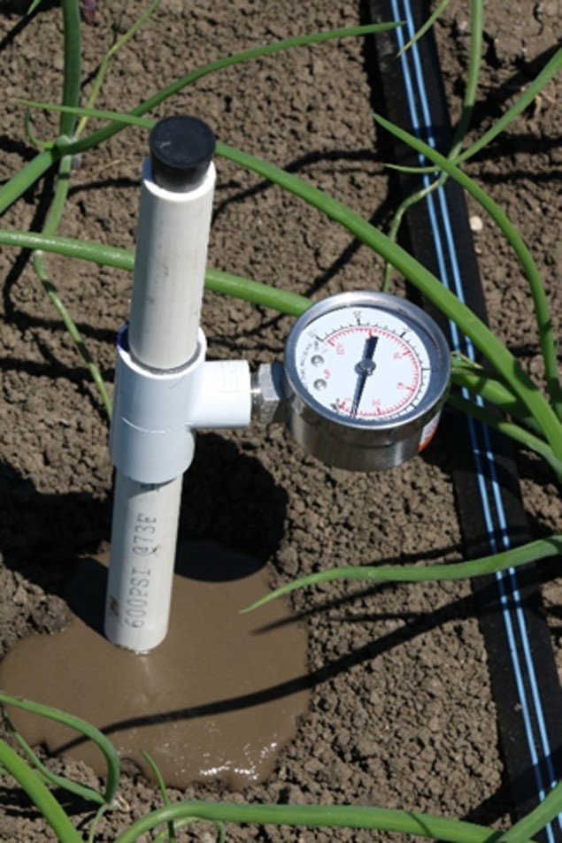
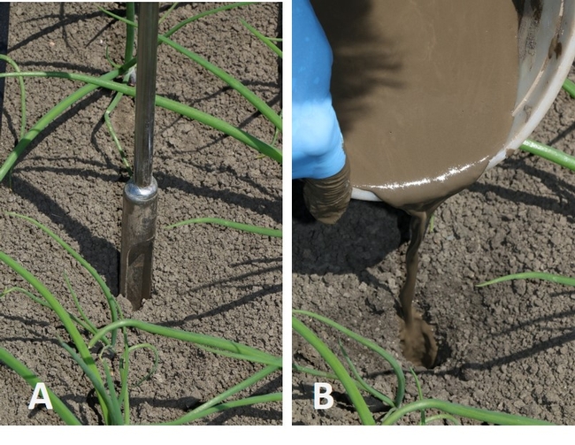
Proper installation of a tensiometer in the field will achieve close contact between the ceramic cup and surrounding soil. Using a soil probe with a ½ inch diameter shaft, make a pilot hole to a depth a few inches shallower that the depth of installation (Fig. 7). Make a soil water slurry by thoroughly mixing soil with the water to a pancake batter-like consistency. Add some slurry into the hole and push the tensiometer to the desired depth (Fig. 8). The soil slurry assures that water can freely move between the ceramic cup and the surrounding soil and fills the voids between the hole and tensiometer shaft. Formation of air gaps between the ceramic cup and the soil will lessen the accuracy of tensiometer readings. After two days of equilibration, the tensiometer reading should accurately reflect the tension of the soil.



Thanks for your comment Mark,
I use a voltage output pressure transducer (RSU-V)sold by irrometer Inc. to interface the tensiometer with a datalogger. I have been having very good luck with these transducers interms of stability over time and accuracy.
Michael Cahn
The epoxy/hardener was recommended by soil moisture corp. because it bonds PVC to ceramic materials. We did not try other epoxy products. You might experiment with a similar type of epoxy.
I understand your concern with buying the expensive epoxy and hardener. It works well and can be use for gluing many tensiometers but has a limited working life time (1 year).
You can try other epoxy products that are suitable for plastic and ceramic. I suggest to experiment with whatever brand that you choose on one tensiometer first. I have used these expoxies in the past but soil moisture corp. cautioned us against the off-the-shelf epoxy products. One problem that we had was that the epoxy did not harden sufficiently and bond well to the pvc.
If you have specific questions you can contact me at mdcahn@ucanr.edu
What values on the meter would you say is dry and wet?
For vegetables and berries, readings less than 20 to 25 kPa are considered moist. Dry conditions would be greater than 60 kPa (cbars). Tensiometers typically have readings less than 5 or 10 kPa after irrigating, corresponding to very moist conditions.
Yes we routinely connect the tensiometer voltage output transducer to Campbell scientific dataloggers (models CR300, CR206, CR1000). Using a cell phone modem connection to the dataloggers, we automatically import and display tensiometer data in the free CropManage software developed and maintained by UC Cooperative Extension (cropmanage.ucanr.edu). Other types of dataloggers could also be used with the tensiometers but I use the Campbell loggers.
Years ago I came across an article by Mr. Thalheimer that described a home built tensiometer utilizing a pressure sensor, read by an Arduino Board. The program was designed to log data in its memory for later evaluation. Should you be interested to learn mire about Martins work, follow the link below to researchgate that publishes the free article. The Arduino SW is also available from him by asking. I hope this bit if info might be helpful to you.
I built a simple tensiometer with vacuum gauge and it works well.
https://www.researchgate.net/publication/274776721_A_low-cost_electronic_tensiometer_system_for_continuous_monitoring_of_soil_water_potential/fulltext/563eb81108ae8d65c0144831/A-low-cost-electronic-tensiometer-system-for-continuous-monitoring-of-soil-water-potential.pdf?origin=publication_detail
Regards,
Gerhard
Thank you for your comments. We did publish a short article that evaluate the accuracy of several flowmeters for metering fertilizer in a previous blog. We more recently have evaluated the accuracy of several models of larger flowmeters including an ultrasonic model from netafim. That article should be published in a few weeks.
https://ucanr.edu/blogs/blogcore/postdetail.cfm?postnum=58011
Thank you for your comments. We did publish a short article that evaluated the accuracy of several flowmeters for metering fertilizer in a previous blog. We more recently have evaluated the accuracy of several models of larger flowmeters including an ultrasonic model from netafim. That article should be published in a few weeks.
https://ucanr.edu/blogs/blogcore/postdetail.cfm?postnum=58011