What kinds of structures will you have at your farm?
Back to production guide main page
When planning and designing your urban farm, think about what structures you will have right away and what other structures you may want to add at a later date. You may want to build high tunnels, a storage shed, a protective covering for a fertilizer tank, a restroom, a dining area, a produce stand, etc.
Building High Tunnels
Steel High Tunnels
We purchased three 12 ft × 60 ft high tunnel kits for $969.99 each from Bootstrap Farmer. The materials that were included in the kit are shown in Table 1 and those that were purchased separately are shown in Table 2. The tunnels were mainly built by two individuals. The more people you have helping, the better, but we would not recommend doing this on your own.
Table 1. Steel high tunnel materials that were included in the kit from Bootstrap Farmer.
Item | Purpose |
Self-tapping screws | For securing ridgepoles together and cross connectors to ridgepoles |
¼” nut driver | For self-tapping screws |
2” hex bolts | For securing ground posts and hoops |
Lock washer | For securing 2” hex bolts to ground posts |
Nut | For securing 2” hex bolts and carriage bolts |
7/16” nut driver | For 2” hex bolts |
4” carriage bolts | For securing baseboards to ground posts |
Washer | For securing carriage bolt to baseboard |
2 ½” Phillips head wood screw | For end walls |
1 ¼” Phillips head wood screw | For lock channel |
6 mil plastic | For covering the high tunnel |
Spring wire | For securing plastic |
Lock channels | For securing plastic |
Cross connectors | For where ridgepoles cross hoops |
End connectors | For the end of the ridgepoles |
Ground post driver | To protect the end of the ground post |
Tape | To repair tears in plastic |
Instructions |
|
Table 2. Materials to build the steel high tunnels that were purchased separately.
Item | Purpose |
8-ft H x 2-in W Silver Galvanized Steel Line Fence Post | Ground posts |
10 ½ ft W 17-Gauge Galvanized Steel Chain Link Fence Rail | Hoops and ridgepoles |
1-in x 6-in x 8-ft Unfinished #2 Whitewood Board | Hip boards |
Hacksaw or electric saw | Cutting ground posts and wood |
Electric drill | Drilling holes, screwing in screws |
¼” drill bit | For drilling holes in ground posts |
7/16” wrench | For securing 2” hex bolts |
Mason line | For installing ground posts in line |
250’ tape measure | For measuring high tunnel dimensions |
Post driver | For driving posts into the ground |
Duct tape | For covering the end of ridgepoles |
Ear protection | For driving in ground posts |
Eye protection | For drilling into steel and wood |
Hand protection | For all activities |
Cutting, Marking, and Drilling Ground Posts
A handheld battery-powered reciprocating saw was used to cut the 8 ft ground posts in half and a handheld battery-powered drill was used to create the ¼ in holes in the ground posts. One hole was drilled 23 in from the end of the pole and the other hole was drilled 2 in from the same end of the pole, rotated 90° from the previous hole. Note that the hole 2 in from the end, which will be at the top end sticking out of the ground, is to secure the hoops to the ground posts and must be running parallel to the placement of the ground posts to avoid coming in contact with the plastic. This hole should only be drilled through one side of the pole at the start. The hole on the other side will be drilled in later when the hoops are secured to the ground posts.
The hole in the middle of the ground post, 23 in from the end of the pole, which will be near ground level once the pole is in the ground, must be placed 90° from the hole at the top. Though it is described in the manual as being a drain hole, which is misleading, this hole will be used to secure the baseboards so it must run parallel to the hoops, perpendicular to the ground posts, and can be drilled through both sides of the post.
New holes can be drilled if a hole is placed incorrectly, however once the posts are in the ground it is more difficult to drill the holes and we ran through several drill bits while doing this. Pre-cut ground posts with pre-drilled holes are available from Bootstrap Farmer but cost nearly twice as much as buying, cutting, and drilling your own. According to the instruction manual they only have the top hole drilled. It took a group of 4 people about 2 hours to mark, cut, and drill all the ground posts for three high tunnels, so this was much more cost-effective.
Marking and Drilling Ground Holes
The dimensions for each high tunnel were measured using a measuring tape reel and marked off using flags. The corners of each high tunnel were marked and then each ground post was marked with 4 ft spacing between the corners. We measured 12 ft for the ends of the high tunnels and 60 ft for the sides. We then measured 61 ft 2.16 in for the diagonals and adjusted the sides and ends as needed if the diagonals were not the correct length.
The ground at our field site was incredibly compact and we found it necessary to drill holes into the ground prior to driving the ground posts in. A 2 in x 32 in auger drill bit (B0BH473V9F, K-Brands) was used for drilling holes into the ground (Figure 1). If the ground was particularly difficult to drill into, we started to drill a hole and then filled it with water to allow the ground to soften before continuing to drill the hole. Sometimes this had to be done multiple times but overall, it made it much easier to drill to our desired depth, which was about 1 ½ ft to 2 ft.

Installing Ground Posts
Once the hole had been drilled to a sufficient depth, the provided ground post driver was used to protect the end of the post and a handheld post driver was used to drive the posts into the ground, making sure the pre-drilled hole in the center of the post was facing towards the interior of the high tunnel and the hole at the top of the post was facing towards the adjacent ground post. The four corner posts were installed first and then the entire area was remeasured and adjusted to make sure the hoop hose was squared off correctly.
Once properly squared off, mason line was tied from corner to corner along the long sides to ensure that ground posts were installed properly in line. Each ground post was then installed with 4 ft of space between each post.
Bending Hoops
Steel poles for the hoops were bent using a hoop bender from Bootstrap Farmer. The hoop bender was secured to an elevated surface and each pole was marked first at 9 in from the end and then every 18 inches. These marks signify how far to insert the pole into the hoop bender for each bend. The pole was then bent every 18 inches, and was checked at each mark to make sure that it was level so that when it was bent it did not become warped in one direction. Scrap pieces of wood can be placed to help ensure the pole is level. Once you get close to the end of the pole, the pole extension can be used for additional leverage.
Once hoops were bent, two hoops were connected on the level ground and secured using a provided self-tapping screw placed on the side of the hoop. Make sure the screw is not placed on the top of the hoop because this can easily catch on the plastic. The nut driver needed to install the self-tapping screw is included in the kit. We found that connecting and securing hoops on the ground was easier than connecting and securing once they were placed in the ground posts.
Installing Hoops
Once the hoops are securely connected, place them in the ground posts at the desired height. Hoops can be placed so the 9 in mark is flush with the top of the ground post, but this may need to be adjusted if the high tunnel is being installed on an un-level surface. Walk around the high tunnel to ensure that all hoops are placed at the same height. Once the hoops are in a satisfactory position, use the ¼ in drill bit to drill through the pre-drilled hole at the top of the ground post, into the hoop and through the other side of the ground post. One person may need to hold the hoop while another person drills to ensure that it remains at the correct height. Once the hole is drilled, secure it with a 2 in hex bolt, a lock washer, and a nut. The nut driver for this nut is also included in the kit.
NOTE: We found that it was helpful to hold one of the ridge poles up at the top of each hoop prior to installation to make sure the hoops were being installed at the correct height. We did a little back and forth between installing hoops and installing ridgepoles to ensure they were installed at the proper height.

Installing Ridgepoles and Cross Connectors
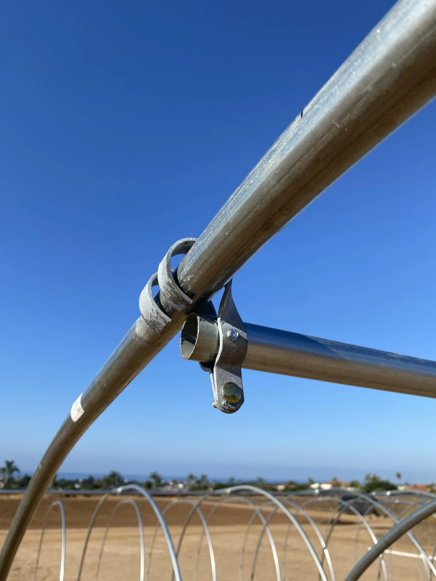
The same poles that were used as hoops were also used as ridgepoles. Each ridgepole was installed one at a time with the associated cross connectors (Figure 2). Once one ridgepole was installed, the next was connected and installed. Self-tapping screws were once again used to secure the ridgepoles, making sure to place the screw on the side rather than the top of the pole (Figure 3). Though there should be some room between the ridgepole and the plastic, this placement of the screw helps to ensure that the plastic will not catch on the screw.

End connectors were then placed on the first and last hoop of the high tunnel to secure the hoop to the ridgepole. Any excess ridgepole should be cut off prior to securing the end connector. The loops of the end connector should open towards the outside of the high tunnel and the ridgepole should fit into the area above the bolt. Self-tapping screws can be used to secure the connector to the ridgepole once it is in place, and then the loops can be bent around the hoop using a hammer or clamp (Figure 4).
Installing Baseboards
Baseboards can be installed to provide additional structure and for securing plastic, netting, or equipment for roll-up sides. We decided not to install baseboards on our high tunnels.
Installing Hip Boards
Hip boards were installed close to where the ground post and hoop come together. The first foot was cut off of the first hip board so that it wouldn’t end on a ground post. Each hip board was then clamped to the outside of the two posts that it would be connected to, making sure to keep it level. Then the 1/4 in drill bit was used to drill through both sides of the hoop and into the wood. The board was then secured to the post with a 4 in carriage bolt, washer, and nut (Figure 5). Though the high tunnel will not have roll-up sides, the hip boards were placed on the outside of the hoops so the plastic can be secured here.

Installing Lock Channels
The lock channels, also called wiggle wire channels, were installed on the hip boards, running flush with the bottom edge of the hip board (Figure 6). Each 6 ½ ft channel was secured with four 1 ¼” Phillips head wood screws drilled in through the wood so that the head of the screw was on the outside of the tunnel.
Once all of the channels were secured to the hip boards, three channels each were secured to the first and last hoops of each tunnel (Figure 7). One of the channels needed to be cut with a hacksaw to fit correctly Self-locking screws were used to secure the lock channel to the hoop.


Installing Plastic and Wiggle Wire
The 28 ft × 60 ft piece of 6 mil plastic was removed from the box and fully unfolded so that the side marked ‘inside’ was facing down on the ground. Don’t worry if the side is not marked ‘inside’, either side of the plastic should be fine facing either way. For tunnels where there was space on one side of the tunnel, the plastic was moved next to the tunnel and then lifted over the tunnel. For tunnels in the middle, where there was little room on either side of the tunnel, the plastic was laid out in front of the open end of the tunnel and was lifted over the tunnel. This step was most easily completed with three people: one person on either end of the high tunnel and one person in the middle of the high tunnel, on a ladder.
The plastic was adjusted so that there was the same amount of extra plastic on either side and end of the tunnel. The plastic was secured to the channel at one end of the tunnel and was then pulled taught and secured to the opposite end. As the plastic was pulled taught, the 6.5 ft long and 1.25 in wide wiggle wire was pushed into the wire channel so that the plastic was between the wiggle wire and channel (Figure 8). The plastic was then secured to the channels on the hip boards, pulling it taught as it was secured.
Excess plastic on the ends of the high tunnels was cut off so the plastic was flush with the hoop. Excess plastic on the sides of the high tunnel was rolled up facing the inside of the tunnel. Four-inch handy hooks (01209, Everbilt) purchased from Home Depot were used to hold the rolled up plastic in place (Figure 9).
NOTE: The wiggle wire tends to sway back and forth as it is weaved into the channel so make sure to wear eye protection. Wear gloves to protect your fingers from getting caught between the wire and the channel.


Installing Door and End Walls
We decided not to place a door or end walls on our high tunnels, but they can be constructed if necessary. The provided manual has instructions for installing the door and end walls, and Bootstrap Farmer has videos online with further information.
PVC High Tunnels
Building the PVC high tunnels was much less expensive and less labor-intensive than building the steel high tunnels. We had enough leftover hardware from the steel high tunnels that we used to build the PVC high tunnels. The materials that we needed to buy are shown in Table 3. The tools and hardware we used to build the steel high tunnels were also used to the build the PVC high tunnels.
Table 3. Materials purchased to build PVC high tunnels.
Item | Purpose |
8-ft H x 2-in W Silver Galvanized Steel Line Fence Post | Ground posts |
1 in. x 20 ft. PVC Schedule 40 Belled-End Pressure Pipe | Hoops |
10 ½ ft W 17-Gauge Galvanized Steel Chain Link Fence Rail | Ridgepoles |
1-in x 6-in x 10-ft Unfinished Whitewood Board | Hip boards |
White Pipe Clamp Schedule 40 Rigid PVC Material Clip | To secure plastic to end hoops |
Installing Ground Posts
Holes were drilled into the ground and steel ground posts were installed in the same manner as for the steel high tunnels.
Installing Hoops
Twenty-foot-long 1 in diameter PVC pipes were installed about 9 in deep into the ground posts.
Installing Ridgepoles and Cross Connectors
The same steel poles that were used as hoops in the steel high tunnels were also used as ridgepoles for the PVC high tunnels. With the poles down on the ground, two poles were connected using self-tapping screws and then installed using two 8 in cable ties crossed one over the other to secure the ridgepole to the PVC hoop, as shown in Figure 10. Once one ridgepole was installed, the next was connected and installed. Though there should be some room between the ridgepole and the plastic, this placement of the screw helps to ensure that the plastic will not catch on the screw. Self-tapping screws were also installed on the PVC hoop to help keep the zip ties and the entire ridgepole from sliding down the hoop, as shown in Figure 10.

Installing Hip boards
Wooden boards measuring 1 in x 6 in x 10 ft were installed as the hip boards. They were placed on the outside of the high tunnel, at a height so the top edge sat flush with the top of the ground post. A ¼ in drill bit was used to drill through the wood, steel ground post, and PVC hoop all at once. A 4 in carriage bolt, washer, and nut were then used to secured the hip board to the ground post and hoop, with the bolt and washer on the inside of the high tunnel.
Installing Lock Channels
The full-length metal lock channels and wiggle wire were used to secure the plastic to the hip boards as described for the steel high tunnels.
Installing Plastic
Unlike with the steel high tunnels, the full length of the metal lock channels could not be installed securely to the PVC hoops at either end of the tunnel. At first, the plastic was pulled taught over the hoop and secured with several 1 in PVC clamps. After a rainstorm with high winds, the plastic came out from the clamps so we needed to secure it in more permanent way. The plastic was either secured with a 1 ft piece of metal lock channel with wiggle wire or the PVC clamp was screwed into place using a 1 ¼” Phillips head wood screw, as shown in Figure 10. The metal lock channel and wiggle wire were cut into 1 ft sections and 1 piece was installed on either side of the hoop, as shown in Figure 11.


Laying Ground Cover
Landscape fabric was used as ground cover to provide a stable surface for the containers, provide a safe, walkable surface for visitors, and prevent the plants from growing roots into the ground. We chose to use 3.2 oz landscape fabric (GR-DLX-1030, Greenhouse Megastore, Danville, IL) and installed it after the high tunnels were assembled (Figure 13). The fabric was laid out either under the high tunnel or in the outdoor area and cut as needed, then secured into the ground using garden staples (GR-GS-ST500, Greenhouse Megastore, Danville, IL) (Figure 14). Ground cover can be installed before or after the high tunnel is built.

